|
INSTRUCTIONS
FOR PART # 1328 THIS
KIT IS DESIGNED TO ADAPT A 1964- 72 GM 10 OR 12 BOLT REAR AXLE ASSEMBLY
INTO A 1978-87 GM G-BODY CHASSIS. THE ONLY THING THAT WILL VARY ON THE
REAR AXLE WOULD BE THE WIDTHS FROM YEAR TO YEAR.
ALL THE MOUNTING BRACKETS WOULD BE THE SAME FOR 1964-72. IF YOU CAN'T FIND ONE THE RIGHT WIDTH, YOU CAN USE A WHEEL
WITH A DIFFERENT OFFSET OR HAVE THE HOUSING AND AXLES SHORTENED. 1. Jack up the car and place on four (4) jack stands. 2. Soak all bolts on the upper and lower arms, sway bar, shocks and brake line with penetrating oil if necessary. 3. Unbolt the lower shock mounts. Then lower the rear end down and remove the coil spring, unhook the brake line and emergency brake cables. Then unbolt the upper and lower control arms from the chassis and remove the rear end. 4. Before installing the A-body rear end, this would be a good time to install new upper bushings. Next you will have to use a torch and grinder to remove the stock spring seats from the axle tubes and weld on the new ones supplied with the kit. Weld them in place using the dimensions shown in Figure 1. This would also be the time to weld on the shock mounts as shown in Figure 6 or you can do it after the rear end is installed. That's up to you. 5. Install the upper control arms into the chassis left and right as shown in Figure 2 using 12rnm x 90mm bolts, lock washers and nuts supplied with the kit. 6. Using a floorjack, lift the rear end in place into the upper control arms and install ½” x 3 ½" bolts, lock washers and nuts supplied with the kit. Do NOT tighten. 7. Next install the lower control arms and brackets using the 12mm x 90mm bolts in the front and the ½” x 3 ½" bolts in the rear with the lock washers and nuts supplied in the kit as shown in Figures 3, Figure 4 and Figure 5. Do NOT tighten. The lower arms are made as lefts and rights and that is the only way they fit. If you install them on the wrong side, the rear bolt holes will not line up with the bracket holes. 8. With everything bolted in place, you can reinstall the coil springs, then jack the rear end up and install the shocks and wheels. 9.
Now the next thing is to check and set the pinion angle. To do this you
will have to take the car off the jack stands and place the car on four
(4) blocks or car ramps or equal height (one under each wheel). This is
so the suspension is loaded just the way is it driven. Now you will need
to check and/or set the pinion angle as described in the attached
instruction sheet on setting the pinion angle. To do this operation you
will need a magnetic protractor (angle finder), which you can get from a
local discount store (K-Mart, Walmart, Sears). If you need more pinion
angle, you need to remove plates A and grind or machine a relief where
the plate touches the axle tube (remove about 1/8" at a time). Then
reassemble and check the pinion angle until you get the desired 4-6
degrees including the angle. If you needed less pinion angle, use a shim
between the plate and axle tube to get the desired pinion angle. 10.
With the pinion angle set you can tighten all the bolts. Then drill hole
4 as shown in Figures 3 and Figure
4 with a ½” drill and install the 2 ½” x 1 ¼” bolts, lock
washers and nuts. Torque all ½” bolts to 100 ft/lbs. Torque all12mm
bolts to 75 ft/lbs. 11. Give all grease fittings a shot of grease. Then reconnect the emergency brake cables and brake lines. Bleed the lines. 12. Remove the car from the car ramps and you are ready for a test drive. Good luck! If
you have any comments write:
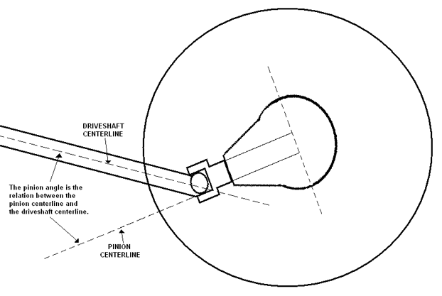
PINION ANGLE NOTE: THIS DRAWING IS AN EXAGGERATION, YOUR PINION ANGLE WILL NOT BE THIS RADICAL.
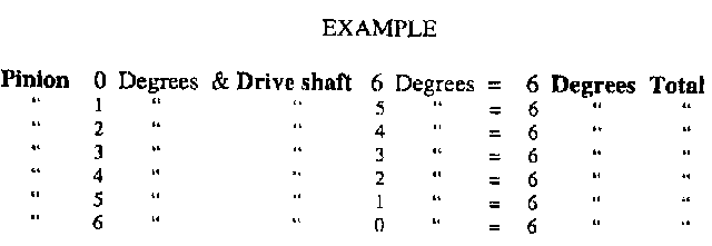
Pinion angle affects the efficiency of the power transmission from the drive shaft to the rear end. The pinion angle is the spread between the pinion centerline and the drive shaft centerline. For maximum performance, the ideal is to have a slight pinion down angle (min. 2 degrees) under full power. Obviously, the pinion angle changes as power is applied and the axle housing begins to twist as the pinion tries to drive the ring gear. Rear axle wind-up can take some of the initial energy or "hit" away from the launch. As a general rule, a leaf spring rear suspension should have between 5-7 degrees of static pinion angle (angle down); and a factory four-link should be set at 4-6 degrees. Keep in mind that these pinion angles are for competition. If you primarily drive your car on the street, you shouldn't have more than a 5 degree angle maximum. The U-joints are designed to run at this angle, which allows the cups to rotate avoiding premature wear and failure. This doesn't affect leaf spring suspension since it runs well within this tolerance. You will need to have the car level on four (4) car ramps or blocks of equal heights so you have room to work under the car when checking the pinion angle. Also, both the front and rear suspension need to be loaded to get accurate readings. The height of the rear end relative to the rest of the driveline will affect the pinion angle. Using an angle finder, which is a tool that combines a bubble level and a protractor, to determine the correct pinion angle for your car. Position the angle finder on the drive shaft and record the measurement. Then place the angle finder on the pinion (the U-joint yoke rotated to vertical position will give an accurate reading) and record the measurement. The pinion angle is a combination of the two measurements.
The
following are fine tuning tips for your suspension: You
can purchase shocks that are 3-position adjustable for both front and rear
applications. These shocks are available from your local speed shop or
mail order supplier. If you can't find shocks designed for your specific
application, you'll have to check in a shock catalog for O.E.
applications. You may have to use shocks from another make or model that
has the same mounts at each end and the same length, or an inch or two
longer. This won't hurt, because it allows for more suspension travel, so
you don't hit the end of your shock travel and pull the rear wheels off
the ground. Coil spring cars, use 90/10 front shocks on small block cars, 80/20 or 70/30 on big block cars and high horsepower small blocks. On short wheel base cars like Mustangs and Capris, use the 80/20 or 70/30 settings. Use 50/50 rear shocks along with an air bag (4-8 lbs air) in the right rear coil spring only. This you will have to play with to find the best setting for your car. The air bag is used to counteract the engine torque wanting to lift the left front corner. CHASSIS
WORK
To
help the effects of the lift bars, especially on unibody cars, you can
greatly improve the chassis reaction by tying the sub frame together with
the sub frame connectors. Also a minimum of six-point cage to stiffen the
chassis up would help. That way the chassis is not absorbing the energy or
hit of the bars. And all that energy will be directed to the tires to help
lay out a bigger footprint. If
you have any comments write: Or
for questions, call our technician, Louie, between 9 AM and 12 noon, Monday
through Thursday at
330-669-9725. FAX to:
330-435-4630. Email
at: [email protected]
or visit the website at www.southsidemachine.com
|


