This really isn't much to report, but I thought I would post it for those that seem to be interested. I did manage to get a little done last week before the stomach virus hit me :-& :
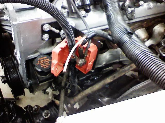
Below is the battery +12V terminal box that mounts on the alternator bracket. It is from the Tahoe harness, and originally distributed power from the battery to the starter and alternator. I moved the Malibu factory wires that were connected to the battery terminal of the starter to this location. The factory Malibu wires connected here provide all the power to accessories, etc. I hate having a big bunch of wires running near exhaust, so I relocated them here. Also, the wire that is not connnected in this picture (yet) is for the fuel pump relay.
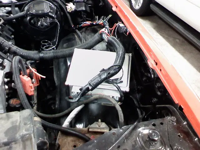
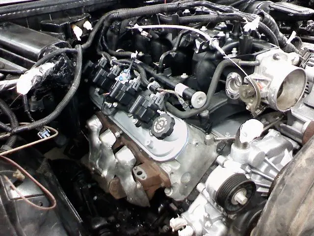
Here you can see "roughly" where the PCM is going to be located on the driver side fenderwell. I need to figure out a way to mount the PCM. I have the Tahoe PCM mount, but it includes a huge fuse panel and takes up too much space. Any suggestions on mounting?
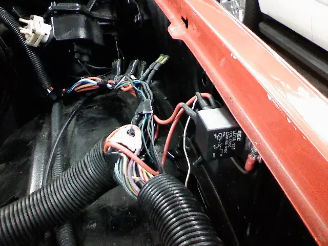
Here is a close-up of the fuel pump relay and some inline fuses that I installed. One fuse is for the battery power to the fuel pump relay. The other 3 fuses are to power different ignition +12V lines that goes to the PCM, Injectors, O2 sensors, other sensors, etc. The guy that did my harness broke it out into 3 separate connections. Each one has a fuse.
Here is a shot of the Lokar 36" LS1 throttle cable. It worked out pretty good. I had to use big flat washers on the firewall and also on the cable bracket because the hole in the firewall was too large and the throttle cable bracket was a large square hole. Looks good anyways. Easy to install, no serious complaints. If you look at the exhaust manifold, there is a hole or location for the smog pump tube. I have fabbed "block off plates", but haven't gotten the bolts yet. I'll show that later.
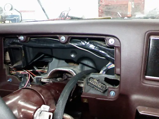
OK, moving inside the car... I removed the gauge pod. Here you can see the factory connector in the bottom right hand corner. This connector has all the signals for the instruement cluster, such as: turn signals, high beam, gauge lights, idiot lights (not going to be used), emergency brake light, etc. If you notice, there is a group of wires in a black sheathing coming out to the left of the cluster connector. These are the wires coming from the PCM/engine harness.
I'm leaning heavily toward using the Nordskog digital gauge package. It is a direct bolt-in replacement for a G-body, has all the gauges, turn signals, high beam, emergency brake light, etc. Since I need an "electrical" speedo (using PCM VSS signal), this makes even more sense. After pricing the gauges, then mounting on a custom plate, wiring etc., this just seems to be a nice solution. It's as cheap or cheaper than gauges, looks pretty cool and will be easy to wire all the gauges and calibrate the speedo. It also comes in different colors (red, green, amber, blue).

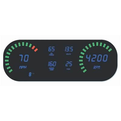
Link here for more info: http://www.nordskogperformance.net/products/auto/dashpanels/detail/dp9255.htm
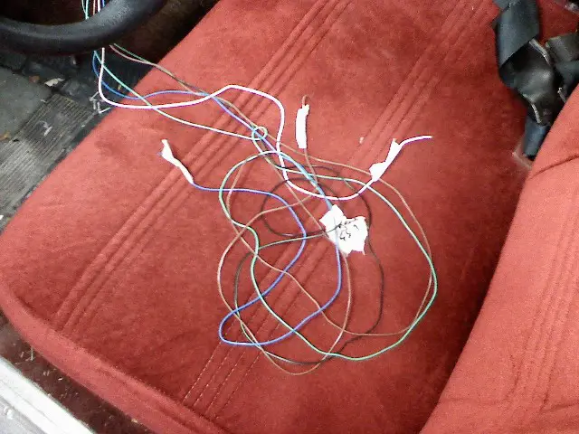
These are the wires coming out from the sheathing. They include VSS (speedo signal), TCC (torque converter control) lockup disable, tach signal, OBDII signal and SES (Check Engine) light.
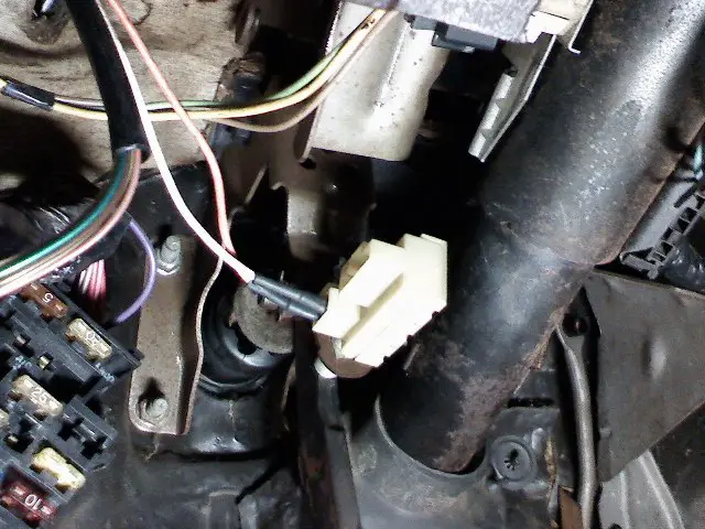
Last but not least. I got the new brake switch installed and partially wired. The brake light wires are connected in this picture. I had to remove the factory Malibu connector and install spade connectors to connect to the new switch. I still need to connect the TCC wire and a +12V signal that will disable power to the torque converter lockup when the brake pedal is pressed. The switch is from a 1996 Camaro, bolts right in, and is only $6.00 at Autozone:
OK, that's it for now. I know, I'm slow as molasses, but we're making steady progress. I'm ready to get this thing fired up and running! Until next time.....
Below is the battery +12V terminal box that mounts on the alternator bracket. It is from the Tahoe harness, and originally distributed power from the battery to the starter and alternator. I moved the Malibu factory wires that were connected to the battery terminal of the starter to this location. The factory Malibu wires connected here provide all the power to accessories, etc. I hate having a big bunch of wires running near exhaust, so I relocated them here. Also, the wire that is not connnected in this picture (yet) is for the fuel pump relay.
Here you can see "roughly" where the PCM is going to be located on the driver side fenderwell. I need to figure out a way to mount the PCM. I have the Tahoe PCM mount, but it includes a huge fuse panel and takes up too much space. Any suggestions on mounting?
Here is a close-up of the fuel pump relay and some inline fuses that I installed. One fuse is for the battery power to the fuel pump relay. The other 3 fuses are to power different ignition +12V lines that goes to the PCM, Injectors, O2 sensors, other sensors, etc. The guy that did my harness broke it out into 3 separate connections. Each one has a fuse.
Here is a shot of the Lokar 36" LS1 throttle cable. It worked out pretty good. I had to use big flat washers on the firewall and also on the cable bracket because the hole in the firewall was too large and the throttle cable bracket was a large square hole. Looks good anyways. Easy to install, no serious complaints. If you look at the exhaust manifold, there is a hole or location for the smog pump tube. I have fabbed "block off plates", but haven't gotten the bolts yet. I'll show that later.
OK, moving inside the car... I removed the gauge pod. Here you can see the factory connector in the bottom right hand corner. This connector has all the signals for the instruement cluster, such as: turn signals, high beam, gauge lights, idiot lights (not going to be used), emergency brake light, etc. If you notice, there is a group of wires in a black sheathing coming out to the left of the cluster connector. These are the wires coming from the PCM/engine harness.
I'm leaning heavily toward using the Nordskog digital gauge package. It is a direct bolt-in replacement for a G-body, has all the gauges, turn signals, high beam, emergency brake light, etc. Since I need an "electrical" speedo (using PCM VSS signal), this makes even more sense. After pricing the gauges, then mounting on a custom plate, wiring etc., this just seems to be a nice solution. It's as cheap or cheaper than gauges, looks pretty cool and will be easy to wire all the gauges and calibrate the speedo. It also comes in different colors (red, green, amber, blue).
Link here for more info: http://www.nordskogperformance.net/products/auto/dashpanels/detail/dp9255.htm
These are the wires coming out from the sheathing. They include VSS (speedo signal), TCC (torque converter control) lockup disable, tach signal, OBDII signal and SES (Check Engine) light.
Last but not least. I got the new brake switch installed and partially wired. The brake light wires are connected in this picture. I had to remove the factory Malibu connector and install spade connectors to connect to the new switch. I still need to connect the TCC wire and a +12V signal that will disable power to the torque converter lockup when the brake pedal is pressed. The switch is from a 1996 Camaro, bolts right in, and is only $6.00 at Autozone:
OK, that's it for now. I know, I'm slow as molasses, but we're making steady progress. I'm ready to get this thing fired up and running! Until next time.....